Imagine designing an extensive infrastructure system where every element—roads, bridges, railways, and even buildings—integrates seamlessly into a unified, functional whole. Achieving this demands not just precision but also a well-organized and transparent framework to manage data, coordinate dependencies, and maintain clarity throughout the process.
This is where knowledge of Spatial Breakdown Structure (SBS) can prove invaluable.
This article serves as a guide to everything you need to know about the Spatial Breakdown Structure (SBS). It explains how, using the IFC 4.3 standard, you can create hierarchical and logical breakdowns for infrastructure projects. You’ll learn how SBS enables more effective model analysis and precise localization of elements.
Disclaimer: After completing my previous article on a similar topic (available here: LINK), I realized I didn’t cover everything I wanted to convey. This piece is therefore both a supplement and an expansion of the earlier content.
Spatial Elements
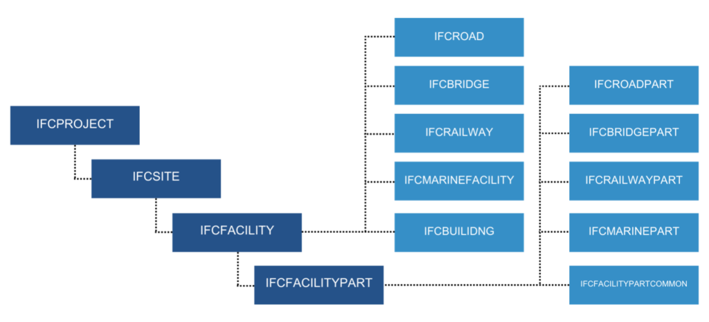
Spatial elements form the foundational organizational structure of a project in the IFC schema. In IFC 4.3, they allow for modeling not only buildings (IfcBuilding) but also various types of infrastructure, such as roads (IfcRoad), bridges (IfcBridge), railways (IfcRailway), and marine facilities (IfcMarineFacility).
The structure of these elements is hierarchical, meaning each object can be broken down into smaller components, creating a logical spatial subdivision. For instance, a building can be divided into storeys (IfcBuildingStorey), which can then be further subdivided into spaces (IfcSpace). Similarly, infrastructure objects can be broken down into parts, such as road sections (IfcRoadPart), bridge components (IfcBridgePart), or railway segments (IfcRailwayPart).
This flexibility enables the creation of spatial models that accurately represent both individual structures and entire infrastructure networks.
Spatial Breakdown Structure, SBS
The Spatial Breakdown Structure (SBS) facilitates organizing models in a way that simplifies their analysis and interpretation. It precisely defines the location of each object within the project space, whether it’s a curb, mast, ditch, or pavement. Geometric elements are assigned to their appropriate positions within the hierarchy, such as a building, storey, or room, and for infrastructure projects—road sections, bridge components, or railway segments.
This structure allows for the quick and efficient localization of model elements, supporting project management and ensuring effective control over its execution.
IfcProject & IfcSite
Every spatial model in IFC must include at least one instance of IfcProject (representing the project as a whole) and IfcSite (representing the project’s location).
An IfcSite can either represent a single area or be subdivided into smaller components, such as individual plots or functional zones (using additional instances of the IfcSite class for this purpose).
The ability to have multiple IfcSite instances within a single project enables the modeling of more complex environments, such as building complexes or integrated infrastructure systems.
I wrote more about it in the previous article: LINK
UsageType
The UsageType attribute for subclasses of IfcFacilityPart (e.g., IfcRoadPart, IfcRailwayPart, IfcBridgePart, etc.) is a mandatory parameter that defines the context or analysis domain of an object. Its application enables the spatial organization of data based on various criteria, such as the overall vertical structure of an object or the detailed longitudinal organization for specific elements, such as tracks. This enhances the model’s flexibility and adaptability to the needs of different industries and specialized analyses.
The introduction of UsageType creates an implicit hierarchy among spatial parts, which, on one hand, increases the complexity of the model but, on the other, allows for more precise representation and management of the object in a multidisciplinary context.
PredefinedType
The PredefinedType attribute in the context of spatial elements enables more precise classification of objects without the need to create additional subtypes. This specific enumeration allows differentiation of elements, such as various parts of roads, railways, or bridges, within existing classes—for example, distinguishing between suspension bridges and arch bridges within the IfcBridge class.
The PredefinedType attribute is important not only for providing information but also for determining the assignment of property sets (Property Sets) and setting rules for how parts are organized. It helps create a more detailed and accurate representation and analysis of spatial object structures.
IfcFacility & IfcFacilityPartCommon
If the model involves objects outside the main categories, such as buildings, roads, railways, bridges, or marine facilities, the general IfcFacility class can be used.
Additionally, the IfcFacilityPartCommon class enables precise definition of smaller components of these objects, such as elements in drainage systems or water and sewage networks.
This makes the IFC standard even more versatile, supporting a wide range of applications in engineering and infrastructure management.
Relations
Spatial elements are connected through the IfcRelAggregates relationship, which defines a hierarchy of elements, such as a building composed of floors, and floors containing rooms.
Geometric objects, in turn, must be linked to spatial elements using the IfcRelContainedInSpatialStructure relationship. This ensures that every object has a clearly defined location within the model.
Additionally, the IfcRelReferencedInSpatialStructure relationship allows for more flexible connections between different parts of the model, providing greater freedom in creating references.
Understanding these relationships is essential for interpreting and using IFC model structures effectively, as well as keeping them consistent and accurate.
Properties
Not only geometric objects but also spatial elements can have property sets (PropertySet) that allow for a more detailed description of the model.
For example, properties such as construction date, industry code, status, level of detail, or maintenance costs can be assigned to an entire building or a road section instead of individual objects.
This makes models more versatile and easier to interpret.
Summary
Building a complex infrastructure project without a plan is like assembling a puzzle without the picture. The Spatial Breakdown Structure (SBS) brings order, helping to understand and precisely organize every element. With the IFC 4.3 standard, engineers can efficiently model and manage complex systems, from roads to railways, transforming chaos into a cohesive and functional whole.
Want to dive deeper into project management with BIM? Check out our other articles!
The post Mastering Spatial elements in IFC 4.3 appeared first on Bim Corner.


